1. Overview
We redesigned the new generation NANO RTK Receiver.
The new version is based on the same D10P RTK module with ESP32-S3 chipset and has more powerful performance.
Even you can develop your own application with this receiver.
It supports Bluetooth (BLE serial).
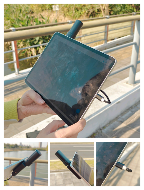
It support working with iPad and iPhone devices.
It supports USB serial port, 6P connector serial port.
Base on the powerful performance of ESP32S3, the new generation NANO RTK Receiver can support more features.
For example, you can set it to connect to a Wi-Fi hotspot directly, and then view and set its various parameters through a web page.
2. Features
- WiFi AP mode for easy setup
- Web page for configuration and status monitoring
- Support working with iPad and iPhone devices
3. Quick Start
How to Quickly Use NANO RTK Device for RTK
Note: Many screenshots and descriptions below are based on firmware from version 1.0.6.dev.300. If your version differs, please refer to the actual behavior of your device’s firmware.
The NANO RTK Receiver Kits include the following items:
- NANO RTK Receiver
- Type-C cable, 1m
- OTG adapter
- 6P GH 1.25 cable, 20/30cm
The OTG adapter is used to directly connect the NANO RTK Receiver to Android phones. It can also be used to power the NANO RTK Receiver when connected to an iPhone or iPad.
The 6P cable is used to connect the NANO RTK Receiver to other devices, such as Ardupilot or PX4.
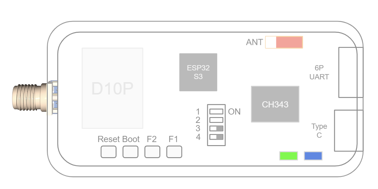
Note: Please note, on the case, the buttons from top to bottom are Boot, F1, and F2.
Default configuration
- USB UART Baud rate: 230400bps
- 6P UART Baud rate: 230400bps
- Output protocol: Rover mode, NMEA 1Hz(GGA,GSA,GSV,ZDA,GST,RMC)
3.1 Configuration and PINOUT
From Left to right:
5V RxD TxD SCL SDA GND
Connector model : JST, GH1.25, 6P
Note
- 6P connector is used to connect to other devices, such as radio devices, or Ardupilot.
- 6P UART Baud rate: 230400bps
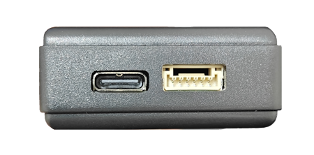
Type C connector is used to connect to Host devices, such as Phone, iPad, or PC.
USB driver is required to be installed when connecting to PC.
Note
- USB UART Baud rate: 230400bps
- If you want to change this baud rate, please refer to this link: change baud rate
3.2 Connect your NANO RTK Receiver
NANO RTK Receiver can be connected via:
- USB
- Bluetooth (BLE)
- WiFi connection
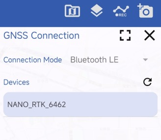
3.2.1 Bluetooth (BLE) connection
NANO RTK Receiver supports Bluetooth (BLE) connection.
Note: we recommend using the SW Maps software to connect to the NANO RTK Receiver.
SW Maps is a free professional GIS data collection software that supports Bluetooth (BLE) connection. It supports RTK devices, such as the NANO RTK Receiver.
You can download it from the Google Play Store or App Store.
It supports Android and iOS devices.
Please refer to the below to find details on how to use SW Maps to connect to the NANO RTK Receiver.
For Android device, SW Maps support Bluetooth (BLE) and USB serial connection.
For iOS device, SW Maps only support Bluetooth (BLE) connection.
The default BLE broadcast name is “NANO_RTK_xxxx”, where “xxxx” is the last 4 digits of the MAC address.
3.2.2 WiFi connection
NANO RTK Receiver supports WiFi connection. It support WiFi AP mode and WiFi sta mode.
In WiFi AP mode, you could connect the NANO RTK Receiver’s WiFi from your phone or PC, which is act as a device like router.
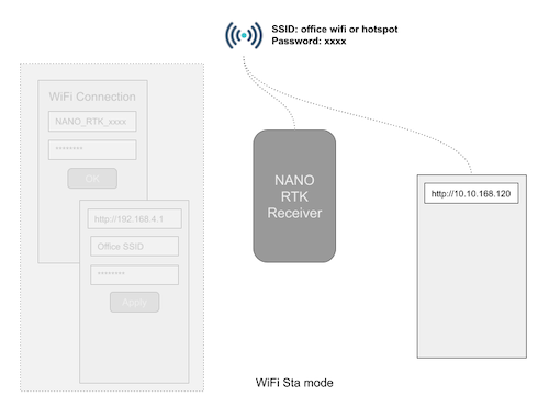
WiFi sta mode is used to let the NANO RTK Receiver toconnect to a WiFi hotspot or office WiFi SSID. Then NANO RTK Receiver will get the IP address from the WiFi router or your hotspot.

NANO RTK Receiver support above two modes by default.
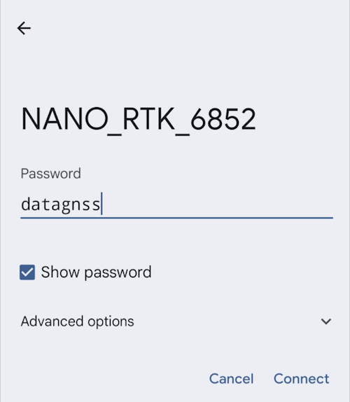
In default configuration, the NANO RTK Receiver will start a WiFi AP with SSID: “NANO_RTK_xxxx” and password: “datagnss”.
When powered on, the NANO RTK Receiver will automatically operate in AP mode, creating a hotspot with the SSID NANO_RTK_XXXX and the password datagnss.
You can connect to this hotspot using your smartphone or laptop. Then, open a browser and enter the URL 192.168.4.1 to access the web page of the NANO RTK Receiver.
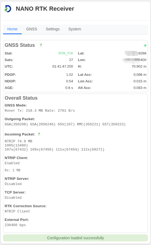
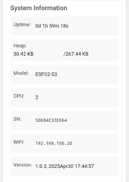
After opening, the webpage appears as shown below:
Note you cannot use a phone to both connect to the NANO’s AP and act as the Wi‑Fi hotspot at the same time. You will need two devices: one to connect to the NANO and another to serve as the Wi‑Fi hotspot.
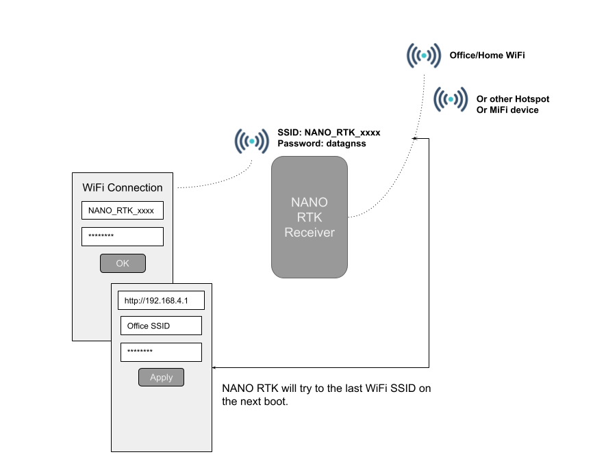
Tap Settings - Scan Button, to scan and get the available WiFi SSID list:
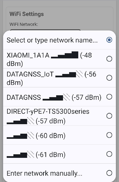
Then select the SSID, input the password, then press connect or save and reboot.
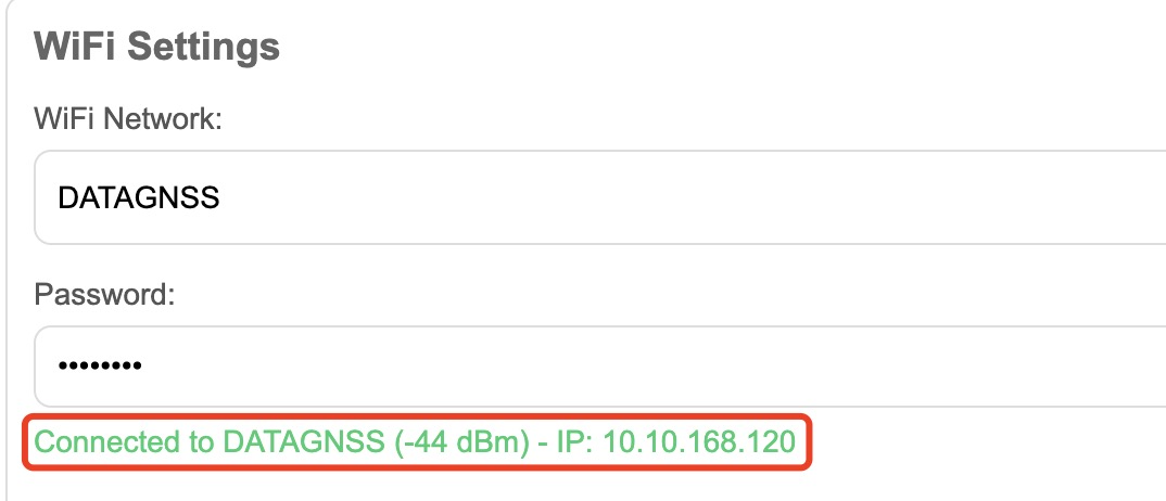
When wifi sta connected, the NANO RTK Receiver will start to get the IP address from the router. The IP address will be displayed on the web page.
You could see the IP address(10.10.168.120) on the above screenshot.
Now you can open web browser, input the IP address (http://10.10.168.120) to view the NANO RTK Receiver’s status with a PC or phone in the same LAN network.
3.2.3 USB connection
NANO RTK Receiver supports USB UART connection on Android phone or Android tablet, or PC.
3.3 Config NANO RTK Receiver
3.3.1 Satrack
Satrack is a user-friendly software that supports NANO RTK Receiver. It could be used to configure and monitor the NANO RTK Receiver. You could use it configure the Baud rate, change the output rate, and more.
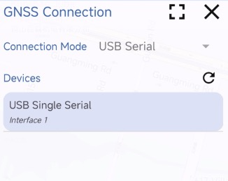
- Connect NANO RTK Receiver to PC via Type-C cable.
- Open the device manager, find the COM port
- Open Satrack software, choose the COM port and set the baud rate to 230400bps. then press connect button.
- If the connection is successful, the software will display the NMEA sentences information.
You could refer to the below link to fine details on how to use Satrack software.
3.3.2 Config NANO RTK Receiver via Web page
In both WiFi AP mode or WiFi Sta mode, you could login to the NANO RTK Receiver’s web page to configure the NANO RTK Receiver.
Login to the NANO RTK Receiver’s web page.
- Homepage
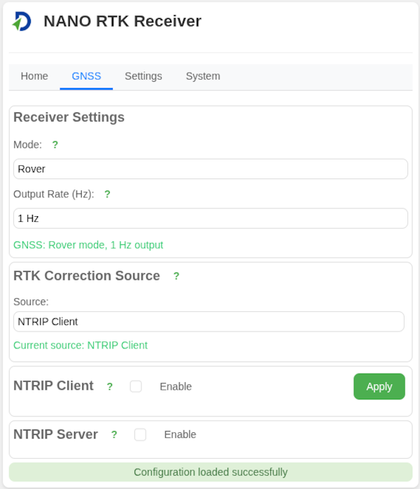
- GNSS
For the GNSS section, there are three modes available in the dropdown menu: Base, Rover and Unconfigured.
In default, the mode is Rover.
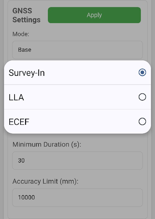
Base In Base mode, the module will automatically be set to Base mode upon startup. At this time, you can also configure how the Base coordinate is obtained.
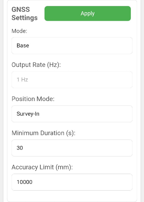
The Base Coordinate supports three modes:
Rover In Rover mode, the module will automatically be set to Rover mode upon startup.
Unconfigured In Unconfigured mode, the module will not perform any operations upon startup. This mode is suitable for scenarios where users need to control the module themselves. In this case, users can connect the Type-C port to a computer, use Satrack to configure the module, and save the configuration. Upon the next startup, the module’s configuration will remain unchanged.
- Settings
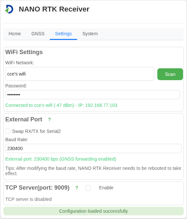
In settings, you can configure the following parameters:
WiFi Settings Configure the WiFi SSID and password.
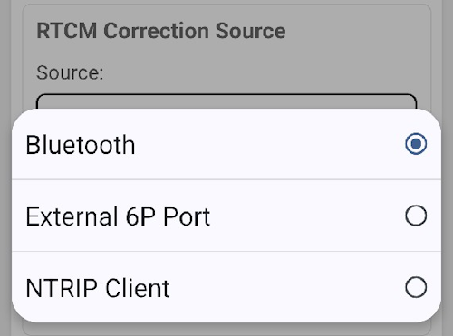
RTCM Correction Source Configure the RTCM correction source.
External Port Configure the external port.
- Swap Rx and Tx
- Baud rate, in default, it is 230400bps.
- System
3.4 Feed RTCM correction data to NANO RTK Receiver
NANO RTK Receiver support to get RTCM data from the following source:
- Bluetooth
- USB UART
- WiFi
- 6P Connector.
3.4.1 Feed RTCM data via Bluetooth
If you connect the NANO RTK Receiver via Bluetooth(BLE), you could feed RTCM data to the NANO RTK Receiver via software like SW Maps.
Then after the RTCM data is received, the NANO RTK Receiver will start to do RTK positioning.
3.4.2 Feed RTCM data via USB UART
If you connect the NANO RTK Receiver via USB UART in SW Maps, you could feed RTCM data to the NANO RTK Receiver via software like above section 3.4.1 Feed RTCM data via Bluetooth.
3.4.3 Feed RTCM data via WiFi connection
If you have configured the NANO RTK Receiver to connect to a WiFi hotspot, you could let NANO RTK Receiver to get RTCM data to from NTRIP caster by NANO RTK Receiver itself.
The NANO RTK Receiver will start to get RTCM data from NTRIP caster automatically when it is connected to a WiFi hotspot.
Follow the 3.2.2 WiFi connection to connect the NANO RTK Receiver to a WiFi hotspot or MiFi.
Then open web browser, input the IP address (like our example http://10.10.168.120)
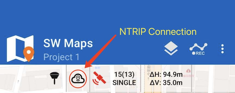
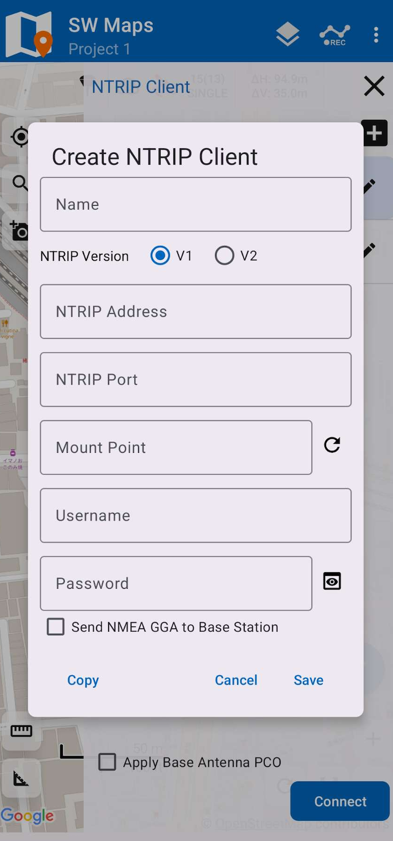
Then navigate to the GNSS page, and set the NTRIP client to be enabled. then input the ntrip client parameters.
Then Apply it.
The NANO RTK Receiver will start to get RTCM data from NTRIP caster automatically.
Now you could navigate to main page, and you will see the ntrip client connection status is Connected and Rx data rate.

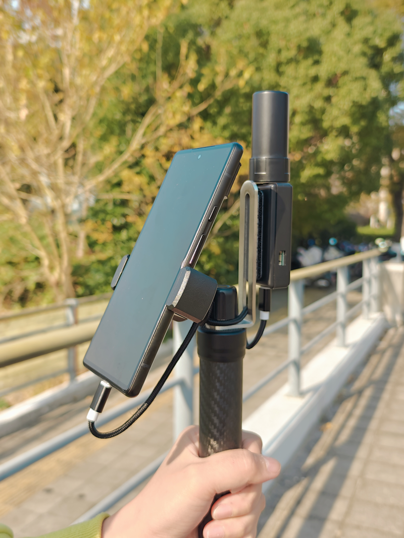
3.5 Work with Android device
Follow the 3.1.2 steps, and then connect your Android device to the Type-C port by OTG USB cable.
For Android devices, we recommend connecting NANO RTK Receiver via Type C cable, which is better and stable than Bluetooth connection.
OTG USB cable refer to this link in datagnss store: USB OTG cable
3.6 Work with iPad and iPhone devices
The details operation steps refer to the below link:
NANO RTK Receiver Surveying and Mapping Kits
4. Update firmware
4.1 update firmware from web [Recommended]
The NANO RTK Receiver is based on the ESP32-S3 platform, offering powerful data processing capabilities and supporting various connectivity options such as WiFi and Bluetooth.
Note: Starting from firmware version 1.0.6.300, upgrading firmware directly from the web page is supported.
By flashing different firmware onto the NANO RTK Receiver, additional functionalities can be achieved.

Choose firmware (*.dgfm, *.dgfw)
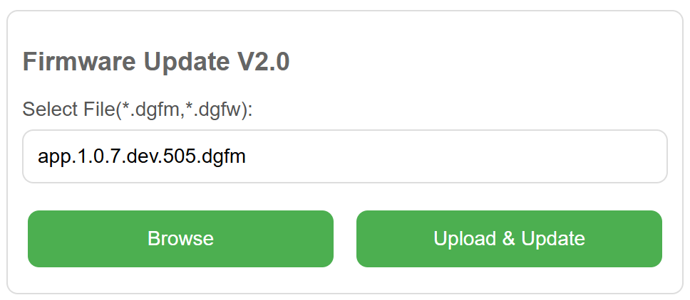
Then press “Upload & Update”

When the progress bar reaches 100%, the upgrade is complete.
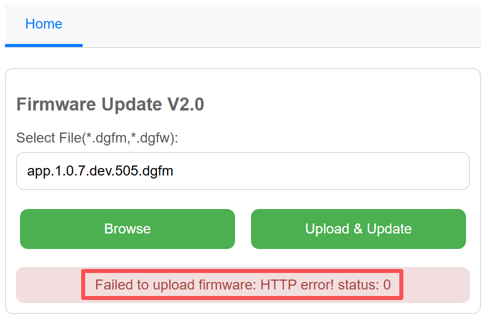
Note: After upgrading to 100%, there is a small chance that the following message may appear: “Failed to upload firmware: HTTP error! status: 0.” In this case, you can ignore the message and press “Home” to return to the homepage.
4.2 update firmware using Flash Download Tool
This section demonstrates how to flash firmware using the official ESP32 Flash Download Tool.
Note: In this mode, you need to open the casing, then set DIP Switch (on board) positions 1 and 2 to ON, and positions 3 and 4 to OFF.
Download the Flash Download Tool from here: Flash Download Tool 3.9.4
Full version (bin files): nano.rtk.s3.15.1.0.7.dev.488.zip
Note: This full version include the combined bin file, please set the address to 0x00 if you flash it with flash download tool.
Note: Before upgrading, please confirm that DIP switch positions 1 and 2 are set to ON, and positions 3 and 4 are set to OFF.
When opening the software, the system will prompt you to select a platform. Here, you need to choose ESP32-S3.
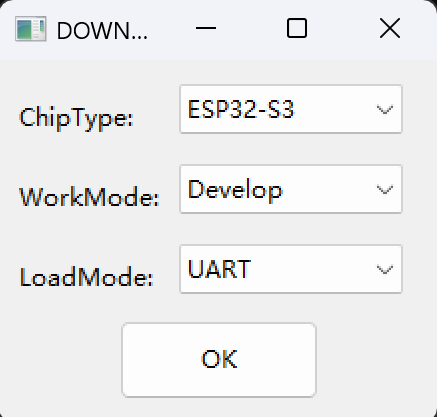
Then open the software and proceed with the configuration.
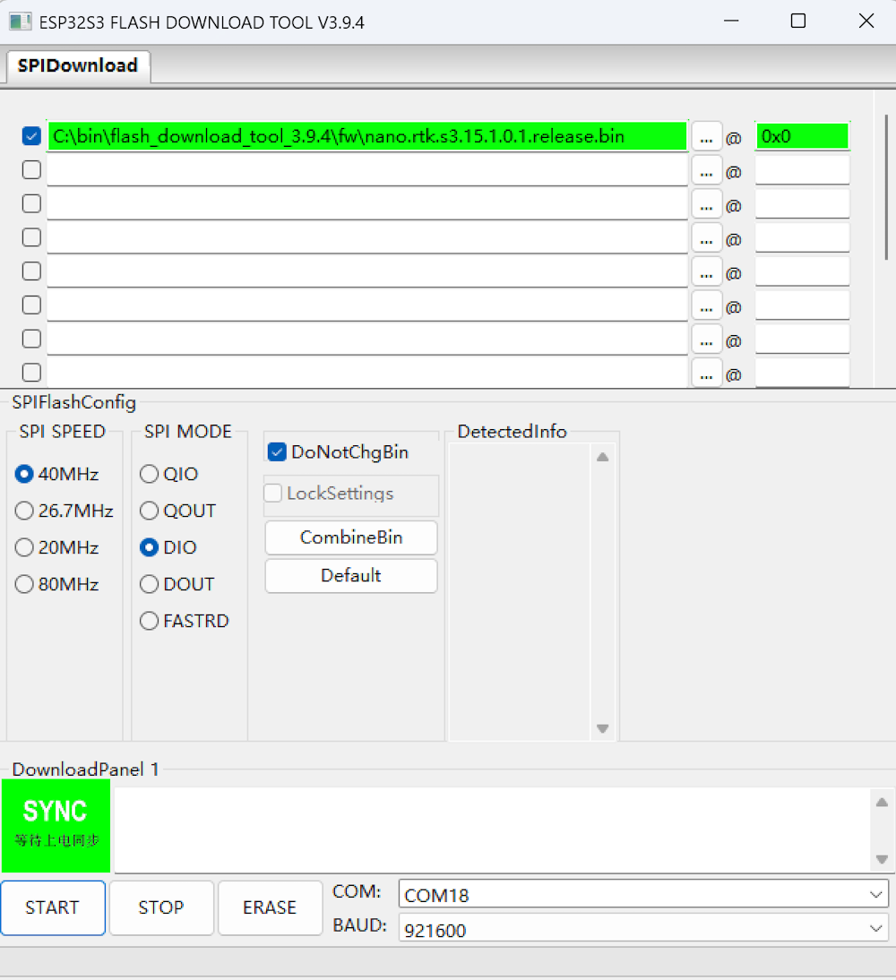
When the green “SYNC” text appears on the UI, press the Boot button on the board to enter Download mode and proceed with the firmware flashing.
Once the flashing is complete, the “FINISH” text will be displayed. At this point, click “STOP” and then exit the program.
Then, press RESET button on the board to reboot NANO RTK Receiver.
Note: After the upgrade is complete, it is recommended to set DIP Switch positions 1 and 2 to OFF, and positions 3 and 4 to ON.
5. FAQS
-
Q: How to change baud rate? A: Please refer to this link: change baud rate
-
Q: How to connect my office’s WiFi? A: Please refer to the section
3.2.2 WiFi connection. -
Q: How to connect the external radio link device, such as 3DR radio? A: Please refer to the section
___.
6. Resource
6.1 Related links
6.2 Firmware
- Latest Firmware:1.0.7.rc.794,for web upgrade firmware